HOME WELCOME SEVEN ELAN ELISE MIDGET TYPE R MINI FAMILY GUEST BOOK
Carbon upgrade Engine upgrade Other upgrades Rear brakes 2004-2006 upgrades Accident rebuild pages Refurb 2014-15
![]()
Over the Christmas/new year break I did several upgrades to the 7. The engine
was removed and a new timing belt, spark plugs and sump gasket were
fitted. More about that later. The gearbox and diff were removed and taken
to BGH in Kent for mods. The wiring from dash forward was ripped out and new
wiring run with new lightweight fuse box. Finally the AP racing calipers were
fitted to the rear, the old calipers, handbrake & cables were removed.
The planning for this Christmas work went on (mainly in my
head) for a few months. I ordered 4 types of wiring conduit (convoluted tube and
spiral binding), numerous wiring connectors, fuse box, relay holders and a
roll of 33amp wire (brown). I got the AP racing calipers in October and the pads
came late November (from performance braking). The cam belt & sump gasket
set were ordered from Burton Tuning several months ago. I keep a stock of oil
filters and Mobil 1 oil.
One of the Lotus 7 Club members (Michael C) arranged a bulk buy of Quaife
alloy gearbox casings and top covers. Michael kindly picked these up from Quaife
and delivered them to BGH ready for me to take the gearbox to them.
On December the 10th I started work. The engine came out in a couple of hours
and the gearbox followed. The bell housing was removed, the box thouroughly
drained and the outside washed and dried.
At this point I started to remove the rear calipers along with the rear hubs
and diff. After the calipers were off I started on the large 41mm hub nuts. The
nearside nut, the left handed thread, would not budge. I broke 2 1/2"drive
"t"-bars. My air gun wouldn't shift it. I borrowed a CP air gun from
the village garage and that moved it a bit (about 1/16th turn) but no further.
The air gun removed the off side easily. By now it was getting dark so I decided
to sleep on it.
Next morning I cut the nut off with an angle grinder and found the thread had
"picked up" when last tightened. I could have cleaned the thread but
decided as it was the left hand threaded shaft and the damage was bad to replace
the shaft. On the Monday I called Tony at Caterham and ordered a new n/s shaft,
a set of rear hub bearings and seals (I was going to get these from a bearing
supplier in Sheffield at about 1/2 the price), 4 spark plugs and a thermostat
gasket (save me making one). "Keep them on the counter for me, I'll be in
tomorrow afternoon"
At 4am on Tuesday 14th December I, with my step-grandson Robert, left home
with a type 9 gearbox in the boot and a Ford 4x4 (ZF) diff on the passenger
floor of an Elise to go to BGH in Kent. Arriving there just after 9am Chris
helped take the bits into their workshop and started stripping the box. A set of
BGH ultra low/close ratio gears were installed in the Quaife casing, a recon
tail casing fitted and the forks where "persuaded" to line up
correctly and ensure a far better gear change than a normal type 9 'box.
At this point, Brian (the genius behind BGH) arrived back from his hospital
appointment. he inspected the old gear set and bearings, concluded they were in
good order and set the price for the "exchange" gearbox. In the
meantime Chris was stripping the Diff. On re-assembly of the large locking rings
he found that one of the threads had picked up some swarf! (Must be catching).
As he had to remove this ring and re-assemble it was decided to keep the diff
there and they would repair the thread properly and send the diff on, before
Christmas.
The diff duly arrived before Christmas.
I can't praise BGH enough. They know what they are doing and are very
professional. The charges are reasonable. I could have stripped and rebuilt the
box and diff myself. Brian said he would do it as they do not sell bits only and
half the benefit was in the way they re-assembled. I didn't see the diff rebuilt
but can confirm they did things to the box on rebuild that I wouldn't. The gear change
is far superior to a normal type 9. For those have remember the Rocket box (as
fitted to the '70's Elan,) it's very close to the click-click "switch"
change. Brian also diagnosed that I used Castrol gear oil. The bearings had
small pit marks on the surface, which he claimed is caused by too much acid in
Castrol oils. I got some Comma gearbox and diff oil on my way back from
Caterham. All my parts were waiting for me on the counter.
Of course at this stage I hadn't driven the car.
So, on the following day it was time to clean down the engine and fit the new
sump gasket. When the engine was turned upside down and the sump removed I found
that Burton had sent the wrong gasket set. A quick call saw the correct gasket
set on it's way and it arrived the day after next. In the meantime I
thought it may be a good idea to show Robert how to change the cam belt. In
taking the time to explain how this part of an engine works I "lost" the
engine timing. I usually paint marks on the pulleys and the belt, remove the
belt and "copy" the paint marks from one belt to the other then fit
the new belt with the paint marks in line. For some reason I couldn't get the
marks to line up so I had to start from scratch, set TDC and the cam pulleys and
jack shaft pulley and fit the new belt. All turned out well but I had to reset
the ignition timing, which, in theory, should have been correct. In practice it
was way out.
Now it was time to finish making the new brackets to bolt the AP calipers to
the rear hub. I had decided to use the 2 front facing hub bolts rather than the
2 top holes on the ear which hold the Sierra calipers. 2 reasons for this. The
top holes are within 2mm centres of the caliper holes therefore making it
impossible to drill the bracket holes required at right angles. The second
reason is that, with the caliper mounted top-bottom the bleed screw can be at
the top thereby making it easy to bleed properly. A day was spent on the
lathe/milling machine making these new brackets.
The following day the diff was re-installed along with the rear hubs (having
fitted the new bearings and seals). The new calipers were also fitted and the
car was now back on all four wheels and could be moved back & forth. As I
have a very small garage/workshop I have to get the car more than half out in
order to get the engine on the crane to refit.
Two days were now spent running the wiring from the dash forwards. (the
scuttle had been removed) The shortest routes were chosen and a lot of
"duplicate" and un-necessary wiring was removed. One example is the
front indicator wiring. 2 pairs of wires run from the dash area to the front
down the off side chassis rail. The nearside pair go across the "X"
frame. Then the second of the 2 pair go all the way back, under the dash and on
to the rear indicators. These type of wiring runs were modified to branch off
under the dash. The wiring to the engine connections on the nearside were routed
under the "through-the-bonnet" exhaust. The wiring to the
front lamps, except the nearside indicator, the new fuse box and the hazard
light socket was complete. Also neatly run were the wires to the coil, brake
light switch, oil pressure sender unit and warning light switch (which are
located next to the pedal box with the hydraulic brake light switch). However
I couldn't finish the wiring to the starter, alternator, fan, water and oil temperature
senders as well as the nearside indicator until the engine was re-installed.
Next morning I asked Lynne to give me a hand refitting the gearbox (Which had
been by our front door all this time since coming back from BGH. Many people
came in over Christmas commented how good it looked, but "what is
it"). I was under the car lifting and sliding the box back whilst
Lynne was to guide the prop-shaft yoke into the gearbox tail shaft. No matter
how much I strained the shaft would not go past the new rear gearbox seal. A
quick phone call and a friend (who is busy rebuilding a 1934 MG PA and building
a bike engined Westfield) came to help. Between the two of us and one big shove
the box slid over the prop-shaft.
The engine was turned on it's head again and the sump gasket fitted. Roger
King used silicone on this gasket, but I've used Hylomar. When the sump was back
on, the engine was put on the crane and refitted. One other mod I had done was
to cut the flexible, braided hydraulic pipe to the co-axial clutch release
bearing in half and re-route it rather than have it go round the battery (under
the carbs) because it was too long. I took my time and used a few extra long
brass nuts to fit the manifold thereby making the job much easier than trying to
get a spanner on the normal brass nuts with were touching the 48mm primary
pipes.
By nightfall I was ready to cut the nearside wiring to length. As I was tired
it waited for the next morning. All went well and in a few hours the wiring was
the correct length with new terminals crimped. All the wiring that had been cut
off and the old fuse box etc had been saved in a cardboard box. Will weighing it
be a disappointment?
I guessed it was about 1.5 kilos. The scales show it's 2.4 kgs. FANTASTIC!
add back the weight of the new wires and fuse box and I've saved 2kgs! The
gearbox is 6kgs lighter and the rear brakes, handbrake and cables weigh in at
6kgs. I'm guessing the car now tips the scales at 520kgs. Not bad for a cast
iron block.
Now to start up.
Oil and water were refreshed and the moment came to press that big red
button. It started straight away but was backfiring and wouldn't rev above 2000
rpm!
I switched off and sat down to think. I was sure the valve timing was correct
as the engine turned over without resistance (plugs removed). If the valve
timing had been out I felt sure I would have felt a valve touch a piston. Sleep
on it Verona. The answer will be clear in the morning.
Good advice. next morning, having thought about it overnight, I slackened the
distributor, started the engine and moved the distributor till I got a better tick over
and some revs. I also got 30,000+ volts up my arm. Connect the timing light, set
the dial to 4 degrees, the tick over to 900 rpm and move the distributor so the
TDC marks line up. Great. Now call Lynne. here comes the problem. I want her to
sit in the car and rev it to 5000 rpm so I can check the timing is 26 degrees.
In a confined space a BDR on full song at 5000 rpm is not exactly quiet. (Of
course "full-song" is 9000rpm) In fact it's extremely, ear
deafeningly, loud! Lynne is terrified. But being the superstar the she is, she
closed her eyes, grits her teeth and does the business. 5000 rpm and 26 degrees
- spot on.
Next day my daughters partner comes round to give me a hand making new brake
pipes and fitting the rear brake bias adjuster and line lock on the tunnel top.
No real problems here and the brakes bleed easily.
Final checks and everything is working. Now to see if the new gear and diff ratios
have made a big difference.
That was on January 3rd at 11am. I'm still not fully sure what it's really
like as we haven't had dry roads here since. However, I get wheel spin in 3rd at
80mph on a damp road. On the M1 It accelerates from 70 to 100mph in 7 seconds.
In any gear it just leaps forward when the throttle is opened (above 4000 rpm).
The rev limiter comes in very quickly (9000 rpm) in second and 3rd.
The brakes are also far more responsive than before. I haven't tried them in
anger from high speed. I'll wait for dry roads for that.
Only problem is the higher revs at "cruising" speeds on the motorway.
Well, you can't have everything, can you?
 The
left hand wires run through the conduit coming out the bulkhead panel under the
oil catch tank.
The
left hand wires run through the conduit coming out the bulkhead panel under the
oil catch tank.
 The
right hand wires are in the conduit running by the side of the pedal box. The
red cable is the battery lead going to the isolator switch and the new fuse box
is on the bulkhead
The
right hand wires are in the conduit running by the side of the pedal box. The
red cable is the battery lead going to the isolator switch and the new fuse box
is on the bulkhead
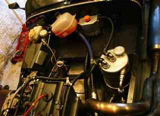
 Overhead
shot with new wiring. The eagle eyed will notice the fuse box is not on the
bulkhead. I fitted it under the dash then had second thoughts and moved it to
the engine side.
Overhead
shot with new wiring. The eagle eyed will notice the fuse box is not on the
bulkhead. I fitted it under the dash then had second thoughts and moved it to
the engine side.
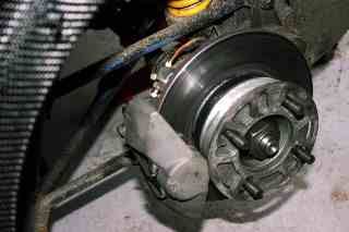 AP
racing calipers with Pagid pads fitted to rear brakes. The caliper is facing
forward.
AP
racing calipers with Pagid pads fitted to rear brakes. The caliper is facing
forward.
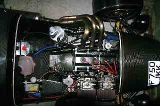
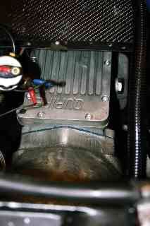 The
new Quaife cased gearbox with BGH internals. The switch with the red and blue
tags is the oil pressure gauge sender unit which is fixed to a bracket on the
brake light switch next to the pedal box. I forgot to take a picture of the all
alloy gearbox before refitting it. I'm not taking it out again to snap (I hope).
The
new Quaife cased gearbox with BGH internals. The switch with the red and blue
tags is the oil pressure gauge sender unit which is fixed to a bracket on the
brake light switch next to the pedal box. I forgot to take a picture of the all
alloy gearbox before refitting it. I'm not taking it out again to snap (I hope).
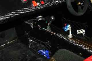 The
tunnel showing the bias adjusting valve & the line lock. The switch on top
of the tunnel is the fuel pump secret switch. Except it's no longer a
secret.
The
tunnel showing the bias adjusting valve & the line lock. The switch on top
of the tunnel is the fuel pump secret switch. Except it's no longer a
secret.
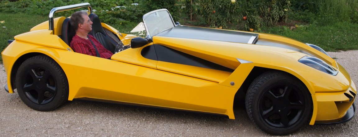
Only in America
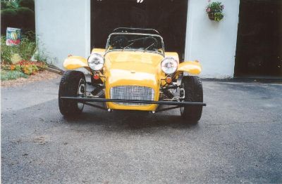
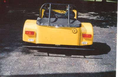
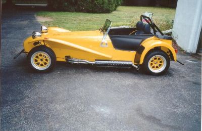
This is how cars in the USA must be modified to get past the regs! Bumpers & side bars!
=======================================================================
THE FOLLOWING ARE THE INSTRUCTIONS FOR FITTING THE SIGNAL DYNAMICS SELF CANCELLING INDICATOR UNIT. IT IS ADVISED THE BATTERY BE DISCONNECTED WHILST WIRING THE UNIT.
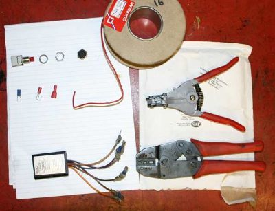 These are the tools, connectors and wire required.
From top left. the switch available from Vehicle Wiring Products on 0115 930 5454. Part No. 24DR (red) or 24DB (black). The nuts come with the switch. I use the hex nut behind dash and the round one on front of dash. The black object next to the 2 nuts is the optional waterproof hood. Switch is ?3.57 each and hood is ?2.71. The roll of wire is 20p per metre or ?2.52 per 300mm roll (single colour to choice of 12 colours). Down one level are the connectors. I use male and female spades and a piggyback. the parts numbers are:
Female: 6.3mm - RFF6 ?1.00 for 10 or ?3.16 for 50. Male 6.3mm - RM6 ?1.00 for
10 or ?2.08 for 50, Piggyback 6.3mm RPG ?1.00 for 10 or ?3.11 for 50. These
part numbers are for red, substitute a "B" for blue or "Y"
for yellow on the first letter of the part number (i.e. BFF6 is the blue female
connector.
The unit at the bottom of the picture has already had the male connectors
fitted. The tool at the top is a wire stripper, a pair of pliers or side cutters
will suffice. The bottom tool is a clamp type crimping tool.
All the connectors referred to above are pre-insulated and part number AM1
crimping tool at ?1.89 will do the job of crimping these terminals to wire. The
tool in the picture is DV5 and costs ?17.35
 This
is the original switch. Tape up the centre wire (green/brown) as this is a 6v
feed from the flasher unit. The green/white (on the left hand) is the rh or off
side flasher light feed and the green/red (on right hand) is the lh or near
side. Both of these are a pair, one to the front and the other to the rear.
This
is the original switch. Tape up the centre wire (green/brown) as this is a 6v
feed from the flasher unit. The green/white (on the left hand) is the rh or off
side flasher light feed and the green/red (on right hand) is the lh or near
side. Both of these are a pair, one to the front and the other to the rear.
Crimp 6 male connectors to the 6 wires on the SD unit. The green/white will
connect to the brown/white and the green/red will connect to the violet/white.
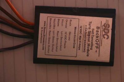 This
is the SD unit. Some of the new ones have the wrong sticker on and the 7th wire
- red/blk, brake light should be ignored
This
is the SD unit. Some of the new ones have the wrong sticker on and the 7th wire
- red/blk, brake light should be ignored
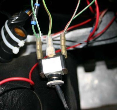
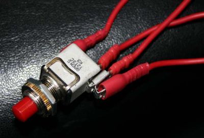 The
new switch. I fitted this one, with the multiple piggybacks, in the hole left
vacant by the old flasher switch
The
new switch. I fitted this one, with the multiple piggybacks, in the hole left
vacant by the old flasher switch
You need a 12v feed for the 2 switches and the unit. I pulled
the cover off the ignition switch and found a switched terminal using a meter
(trial and error will do if you haven't a meter). I then connected a piggyback
terminal crimped to a wire long enough to easily reach the left hand switch.
Then fit the original ignition switch wire back on to the piggyback spade. Feed
new wire through cover and refit cover. Crimp a piggyback to the switch end of
this wire and fit to one of the switch terminals. Then crimp a piggyback
terminal to another length of wire which will go from left hand switch, over
steering column to the right hand switch (see below). Fit this to the piggyback
spade on the wire from the ignition switch. Make up a length of wire and crimp a
female connector to it. The other end of this will have another female terminal
connected and plug into the male connector on the orange wire of the unit. Make
up a short wire (8 to 10 inches) with female connectors on both ends. This wire
will go from the unused terminal on the left hand switch to the violet wire on
the unit. Do same but with a longer wire for the right hand switch with one end
on the unused terminal on the switch and the other connected to the brown wire
on the unit. The right hand switch, with the two wires connected the right hand
switch can now be fed over the steering column awaiting fitting into the
dash.
 All
that remains, as far as wiring is concerned is to connect the black wire on the
unit to earth. I made up a black wire with a female terminal crimped on one end
and connected to the black male on the unit and a round connector crimped on the
other end then fitted to one of the 2 bolts either side of the steering column
where it goes through the bulkhead.
All
that remains, as far as wiring is concerned is to connect the black wire on the
unit to earth. I made up a black wire with a female terminal crimped on one end
and connected to the black male on the unit and a round connector crimped on the
other end then fitted to one of the 2 bolts either side of the steering column
where it goes through the bulkhead.
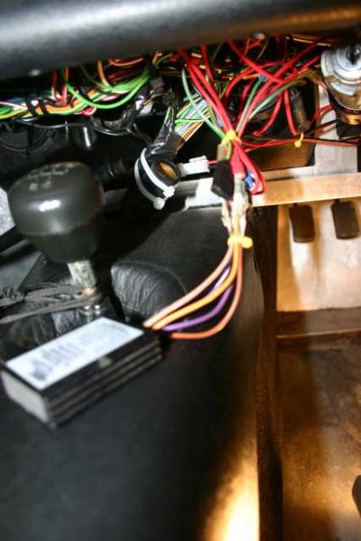
I then tidied the wires by cable tying either side of the 6
connectors to the unit as shown above. The unit was placed on top of the
ignition switch and the wires close to the unit were cable tied to the ignition
switch (to avoid the unit falling down over time).
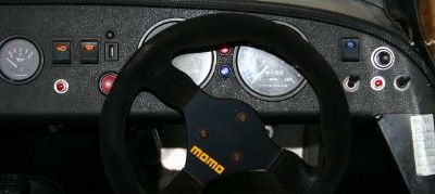 The
final job is to fit the two new switches. The left hand will go into the hole
vacated by the original flasher switch. I fitted the right hand switch between
the headlight dip and flasher switch. If the switch is awkward to get a finger
to the I will swap the headlight flasher switch over.
The
final job is to fit the two new switches. The left hand will go into the hole
vacated by the original flasher switch. I fitted the right hand switch between
the headlight dip and flasher switch. If the switch is awkward to get a finger
to the I will swap the headlight flasher switch over.
Now for a 100 mile blat to test it.
This is a posting from the Boardroom which relates to an install on a
Westfield. The author is Glen H.
Fitted mine a few days ago, for anyone still to fit theirs then below is
how I wired mine up based on Norman's details on his site / link
Normans site clearly details the type of connections that you can use - below
just lists which wires I connected to which on a Standard Westfield CEC loom.
* Orange Wire which is the +ve 12v feed - connect to the Green/white wire of the
looms spare / Auxiliary plug under the dash, this being the ignition switched
feed (was listed as item 26 in the build manual loom details)
* Black Wire which is the -ve / ground - connect to the black wire of the above Auxiliary
plug on the Westfield loom.
* Violet/White wire which is the output to the Left / Nearside side turn
indicator lamps - connect to the looms existing indicator Green/Red wire
(normally used for the standard toggle switch - Item No. 45 in the build manual)
*Brown/White wire which is the output to the right / Offside side turn
indicator lamps - connect to the looms existing indicator Green/White wire
(normally used for the standard toggle switch - Item No. 45 in the build manual
loom details)
*Violet wire which is the 12v input signal to the unit for the left / Nearside
indicators - connect to the Switch wire / load side of the Left turn
button.
*Brown Wire which is the 12v input signal to the unit for the Right / Offside
indicators - connect to the Switch wire / load side of the Right turn
button.
I used the same 12v +ve feed looped from the the Auxiliary feed / orange wire to
feed the new left & right side Momentary Action switches - see Nornams site
for details on using 'Piggy Back' type connections.
Note - for the 12v feed to the unit I did initially try and use the Light
Green/Brown wire of the original indicator switch (item 45 of the build manual
loom details) - this being a 12v feed as opposed to 6V as Normans Caterham
however I found that this confused / dragged down the indicator flasher unit and
the indicators did not work - hence now using the Looms Auxiliary feed
Hope this helps
=====================================================================
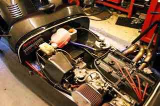
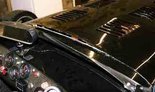 This
is the duct formed by bending the centre 18" of the bonnet from a point one
inch back from the rear edge. The lift is 3/4" up. The idea is to create a
NACA type duct which will form a low pressure area thereby sucking the air from
under the bonnet. So far, on a 700 mile trip, the engine ran cooler and the
tunnel and footwell was almost cold. If it is working, and I believe it is, then
the top speed should be increased and the fuel consumption may be better.
This
is the duct formed by bending the centre 18" of the bonnet from a point one
inch back from the rear edge. The lift is 3/4" up. The idea is to create a
NACA type duct which will form a low pressure area thereby sucking the air from
under the bonnet. So far, on a 700 mile trip, the engine ran cooler and the
tunnel and footwell was almost cold. If it is working, and I believe it is, then
the top speed should be increased and the fuel consumption may be better.
It won't improve your sex life but may make blatting better.
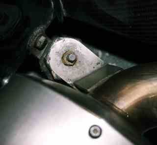 The
correct way to mount the rear exhaust mounting. The right angle bracket is
bolted to the chassis, the bobbin is bolted to the bracket and the bracket on
the silencer sits on top. The bobbin is therefore being held down by the weight.
The alternative method of fitting the bobbin to the chassis and the right angle
to the bobbin will, with the heat generated, separate the metal flange of the
bobbin from the rubber.
The
correct way to mount the rear exhaust mounting. The right angle bracket is
bolted to the chassis, the bobbin is bolted to the bracket and the bracket on
the silencer sits on top. The bobbin is therefore being held down by the weight.
The alternative method of fitting the bobbin to the chassis and the right angle
to the bobbin will, with the heat generated, separate the metal flange of the
bobbin from the rubber.
_______________________________________________________________________________________________________________________________
This is a Westfield as modified by a chap in France, jean-marie courtault who visited the Stoneliegh show in 2012